What Is Building Planning and Drawing
🕑 Reading time: i infinitesimal
Building plans are the ready of drawings which consists of flooring plan, site plan, cantankerous sections, elevations, electric, plumbing and landscape drawings for the ease of construction at site. Drawings are the medium of passing the views and concepts of an architect or designer into reality.
Contents:
- Types of Building Program Drawings
- 1. Site Plan
- 2. Floor Programme
- 3. Cross Section
- 4. Elevation
- one. External Elevation
- 2. Internal Elevation
- five. Mural Plans
Types of Building Plan Drawings
Considering the detailing and complexity of a project, different types of drawings are issued by an builder for the like shooting fish in a barrel agreement and smooth working of structure process. Some the types of drawings are discussed in depth below,
1. Site Program
Site plan is comprehensive detailed drawing of the building or an apartment representing whole plan of a building. Information technology shows property boundaries and means of admission to the site, and nearby structures if they are relevant to the pattern. For a construction project, the site programme also needs to testify all the services connections like drainage and sewer lines, water supply, electrical and communications cables, outside lighting etc.

Fig 1: Site Plan of a house.
Its a first design that is made for whatsoever project earlier going into detailing process. Drawing up a site plan is a tool for deciding both the site layout and the size and orientation of proposed new buildings. These drawings should comply with the local development codes, including restrictions on historical sites. Information technology acts as a legal understanding for the permission of construction from the government torso. For this, it is required that the site plan is fabricated by a licensed professional like builder, engineer, landscape architect or state surveyor.
2. Flooring Plan
A plan means, elevation view of any edifice or object. Floor plan is the about fundamental architectural diagram, a view from higher up showing the arrangement of spaces in edifice in the aforementioned fashion as a map, but showing the organisation at a particular level of a building. Flooring programme view is defined equally a vertical orthographic projection of an object on to a horizontal plane cutting through the building. This shows the walls, windows, door and other features such as stairs, fittings and even piece of furniture as well.

Fig two: 2D Floor Plan.
Floor plan is ordinarily given in 2D form, which has all the measurements and detailing. Now a days for a better understanding and conceptualise the program prior to the construction, floor plans are fabricated in 3D where one can come across how the entire flat looks with furniture from above, giving you a mode to see not only how objects fit in the infinite, simply how specific furniture pieces wait together.

Fig 3: 3D Floor Plan.
3. Cross Section
Geometrically, a cross section is a horizontal orthographic projection of a edifice on to a vertical airplane cutting through the edifice. Cantankerous section is vertical cutting section of any building which shows the details of dimension, thickness of whatsoever component of a edifice. It besides represents the sill peak, lintel pinnacle, floor height and other minute details of a construction.

Fig four: Cross Section.
The section plane where the plan is vertically cutting is represented in the 2d floor plan by a bold dotted directly line.
iv. Elevation
An elevation cartoon is an orthographic projection drawing that shows one side of the house. The purpose of an acme drawing is to testify the finished appearance of a given side of the firm and furnish vertical height dimensions. Majorly it is divided into 3 types,
1. External Pinnacle
Outside elevation is the outside representation of a building. Information technology consists of details of type of finish, floor height and projections if any. Exterior elevations can exist second or 3D drawings. 2nd drawings typically have measurements on them, showing where the relationship betwixt outside elements like doors and lights. 2d elevations likewise can have callouts to unlike kinds of bricks, stones, and paints, so you know exactly where each fabric needs to go.

Fig 5: 2D External Peak.
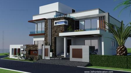
3D exterior renderings are similar to their second counterparts, except they focus entirely on the visual. Almost of the fourth dimension, a rendering is a concept drawing to take to whoever is amalgam your project to give them an idea of what you want the exterior to look like. From the concept, they'll create the detailed exterior elevation they demand to build from.

Fig six: 3D External Elevation.
ii. Internal Top
Interior elevations are very similar to outside elevations in purpose. Elevations are extremely useful when constructing a room such equally a kitchen or bath, which require visualisation of built in elements.

Fig vii: 3D Internal Elevation.
Normally interior elevations are made in 3D that show your article of furniture in your space. The inner tiptop furnishings a lot on the living condition and peaceful mind. These days keen importance is given to interior elevation than exterior elevation. Interior elevation has the paint color, lightning types, furniture design and floor patterns.
five. Landscape Plans
A perfect abode or a building has a lush green garden adjacent to it, which enhances the beauty or aesthetics appearance of the building. Hiring a landscape architect for the adornment of houses is trending at present a days.

Fig viii: Landscape Program
On landscape plans, you'll see everything from flowers to sidewalks and lawn decorations to fountains. It majorly consists of sidewalks, plantations and other decorative features that tin can raise the living area. Read More: Types of Drawings used in Building Construction
Source: https://theconstructor.org/practical-guide/building-plans-types/24963/
Post a Comment for "What Is Building Planning and Drawing"